|
A Practical Twin-T Oscillator - Scroll down. Perhaps the first thing that will strike you (if you have met the twin-T before) is that the input to the twin-T (from the bulb) is actually fed into the foot of the network and output is (as you might expect) from one arm (into the base of the transistor) but the other arm is earthed. Now hold on a minute: an emitter follower has no voltage gain __ Designed by Richard Torrens
A Practical Wien Oscillator - Scroll down. The second circuit is a practical implementation of a Wien oscillator but in this the Wien network is inverted. It is the 'wrong way up' and in the negative feedback path. Positive feedback is applied via the 500R preset to make it oscillate. And there's a nice incandescent light bulb to show that it's working __ Designed by Richard Torrens
A Simple Circuit VFO for 80 & 160 Meters - This VFO is simple to build and is quite stable. The VFO produces a two phase output (2 outputs) , making it well suited to supplying a signal to either single ended RF amplifiers, where only one__
A/V Sender - This small circuit transmitter processes the signs of audio of a sound table or microphone, and the signs of video of a camera, or still the audio signs and video of a DVD, Video-cassette or even it sweats her video plate has an exit of composed video, you can transmit direct of your computer. Playing them in a channel free from the strip of VHF __ Designed by Toni on Aug 19, 2009
Accurate 1hz Generator - Accurate 1Hz squarewave pulses are required in stopwatches and other digital circuits. Here is a low-cost, general-purpose 1Hz signal generator without using a crystal oscillator.230V, 50Hz, single-phase AC mains is stepped...__ Electronics Projects for You
Add phases to Simple Circuit RC oscillator - 08/25/14 EDN-Design Ideas - Demonstrates a simple way to generate a multiphase clock signal, the frequency of which can be varied with minimal change in phase shift (s). The phase shift of the second output can be tuned from near zero to 180° without affecting the frequency. The basic circuit uses a minimum of parts: one cap, two resistors, plus two Schmitt triggers. Design by Einar Abell
Adjustable High/Low Frequency Sine wave generator - This circuit uses the versatile MAX038 function generator. Although in this circuit some of the advanced characteristics of this IC are disabled, you can generate Sine, Triangle, Square waves (adjusting A0 and A1 pins see datasheet on www. maxim-ic. com if you want other waves, use a switch __ Designed by Jonathan Filippi
AF Generator - The sinewave generator is based on 4 op-amps which are present in a single TL084 i.c. (see fig.1). Op-amps A1 and A2 are connected to the frequency determining RC networks R5+P1a/C1 and R6+P1b/C2, respectively. In my version of the generator, P1 is replaced by a stepped attenuator (dual rotary switch with 12 positions, see above). Moreover, I have included two additional frequency ranges; thus, S1 is in my version a dual rotary switch with 5 rather than 3 positions. __ Designed by W.Mieslinger
AIR Transparency Monitor, Xenon Flash Receiver - I designed this receiver circuit many years ago to monitor the quality of a mile long column of air for future optical communications experiments. The transmitter system (circuit 72 below) uses a powerful xenon flash in conjunction with a large 12 inch. . . Circuit by David A. Johnson P.E.-June, 2000
AIR Transparency Monitor-Pg2 - This is Page 2 of the receiver circuit AIR TRANSPARENCY MONITOR, XENON FLASH RECEIVER. . . Circuit by Dave Johnson P.E.-June, 2000
ALD555 Oscillation - Circuit Ideas for Designers App Note__ Advanced Linear Devices, Inc
Amplitude-Stable Oscillator Has Low Distortion, Low Cost - 11/09/00 EDN-Design Ideas - The multivibrator is a common circuit that consists of an amplifier with both positive and negative feedback (Figure 1a). When the output is positive, the positive. PDF contains multiple circuits, scroll to find the one of interest Design by Moshe Gerstenhaber, Chau Tran, and Mark Murphy, Analog Devices Inc, Wilmington, MA
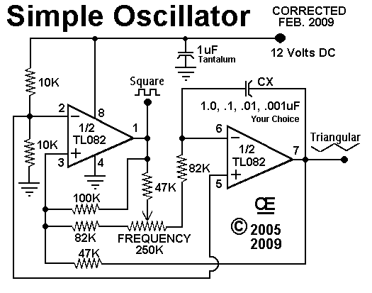
An Oscillator Sawtooth & Square Wave Output - Simple, Single Supply and Works Very well with Minimum Parts Count. __ Designed by G.L. Chemelec
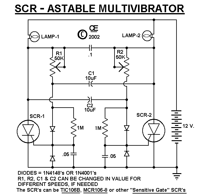
An SCR Flipflop for Alternating Flashing Light Bulbs - Schematic only __ Designed by G.L. Chemelec
An Ultra Low Distortion Audio Test Oscillator - This project was published in the March 2010 issue of the Australian magazine "Amateur Radio", and uses a unique circuit and cheap readily available components to achieve laboratory grade performance. :-) __ Designed by VK5JST / VK5TR
AN-45-001 Automated load measurement of VCO's - AN-450-01 App Note__ MiniCircuits.com
AN-45-002 Line Stretchers Ease VCO Load-Pull Testing - AN-450-02 App Note__ MiniCircuits.com
AN-95-003 Glossary of VCO terms - AN-95-003 Application Note__ MiniCircuits.com
AN-95-004 Wide Modulation Bandwidth Measurements - AN-95-004 Application Note__ MiniCircuits.com
AN-95-005 How VCO Parameters Affect Each Other - AN-95-005 Application Note__ MiniCircuits.com
AN-95-006 Optimizing VCO/PLL Evaluations & PLL Synthesizer Designs - AN-95-006 Application Note__ MiniCircuits.com
Analog LED Bar VU Meter - The circuit was designed to work with an audio power amplifier which operated off +18v-0v-18v power rails. The actual voltage used is not too critical except that the feedback is referred to the LED chain which itself is anchored to a +12v rail, hence the separate stabilizer __ Designed by Richard Torrens
Analog Voltage Controls Digital Potentiometer - 03/20/08 EDN-Design Ideas - A microcontroller with an internal ADC controls a digital potentiometer via an I2C interface Design by Hrishikesh Shinde, Maxim Integrated Products, Dallas, TX
Analyze LED characteristics with PSpice - 01/18/01 EDN-Design Ideas - Recent advances in LED technology have led to LEDs' widespread use in outdoor-signal applications, such as in traffic and railroad signals. A typical LED signal consists of an LED array and a power supply. When a low-voltage power supply is desirable or mandatory, series/parallel combinations of LEDs become inevitable Design by Sam Mollet, GE Harris Harmon Railway Technology, Grain Valley, MO
Anton Chekhov - My LO strategy involved mixing a 16.93 MHz Xtal oscillator ( Xtal Q = ~100K) with a 3.121 to 3.216 MHz Hartley L-C VFO. I planned to use the EMRFD Figure 4.24 method to extract low noise + distortion from the Xtal oscillator and mix it with the VFO signal in a Gilbert cell mixer like the NE612. __ Contact Vasily Ivanenko
Arduino LFO Waveform Generator - This project uses an Arduino microprocessor and a DAC0808 8 bit parallel DAC to produce arbitrary low frequency oscillator (LFO) waveforms. These waveforms are useful for driving a tremolo/vibrato circuit in a guitar amplifier such as the Lil Tiger or a phaser effect such as the Liquidator __ Designed by G. Forrest Cook
Arduino LFO Waveform Generator V2 - This project uses an Arduino microprocessor and a MAX522 8 bit serial DAC to produce arbitrary low frequency oscillator (LFO) waveforms. These waveforms are useful for driving a tremolo/vibrato circuit in a guitar amplifier such as the Lil Tiger or the Hammonator 2RVT. This is a second generation version of this project, see the first version for reference. __ Designed by G. Forrest Cook
Astable Flip Flops - Several circuits here. The familiar astable flip-flop circuit is a handy configuration for making flashers or generating squarewaves. Here is a typical alternating LED flasher with the LEDs in the emitters instead of collectors as is normally done. The bias resistors are directly connected __ Contact: Charles Wenzel of Wenzel Associates, Inc.
Astable Mode Operation 50% Duty Cycle - Circuit Ideas for Designers App Note__ Advanced Linear Devices, Inc
Astable Mode Operation Free Running Oscillator - Circuit Ideas for Designers App Note__ Advanced Linear Devices, Inc
Astable Multivibrator - The capacitor C charges via R1 and R2 and when the voltage on the capacitor reaches 2/3 of the supply, pin 6 detects this and pin 7 connects to 0v. The capacitor discharges through R2 until its voltage is 1/3 of the supply and pin 2 detects this and turns off pin 7 to repeat the cycle__ 555-Timer
Astable Multivibrator - Scroll to find this circuit. This is an astable multivibrator circuits to alternately flash two LEDs. The R & C values determine. __ Designed by Bill Bowden
Astable Multivibrator - As shown in the schematic diagram here, the astable multivibrator simply extends the modification that converted the bistable multivibrator to a monostable version of the circuit. Now, both transistors are coupled to each other through capacitors. Whichever transistor __ Designed by Dr. W D Phillips
Astable Multivibrator Gets Hysteresis From Positive-Feedback Stage - 22-Oct-09 EDN-Design Ideas - Add hysteresis through positive feedback Design by Robert Larson, Seattle, WA
Astable Multivibrator Lights LED From a Single Cell - 08/21/08 EDN-Design Ideas - A classical multivibrator drives a step-up inductor to power an LED from a single cell Design by Luca Bruno, ITIS Hensemberger, Monza, Lissone, Italy
Astable Multivibrator Projects - Astable or free-running multivibrators have been used in home-built amateur radio equipment for many years. The basic circuit is a two stage amplifier with AC-coupled feedback from output to input. One transistor stage is on (conducting current) __ Designed by Todd, VE7BPO
Astable Multivibrator with Very Low Power - This classic circuit draws only 200 nanoamps from a 1.5v supply . . . Hobby Circuit designed by David A. Johnson P.E.-June, 2000
Astable Multivibrators - Multivibrators: an old, well known and boring subject. No - not at all: there are lots of different ways of looking at them and they are not at all what they may seem. __ Designed by Richard Torrens
Astable Ultra Low Power Multivibrator - Taking advantage of some new voltage comparators, this circuit can produce a nice square wave signal while drawing only 1.6 micro amps. With the inclusion of a diode, the circuit can also produce short pulses instead of a square wave signal . . . Hobby Circuit designed by David Johnson P.E.-December, 2004
Audio Test Oscillator - As a piece of test equipment, an audio oscillator has to be considered essential for anyone working in with hi-fi gear. Together with an audio millivoltmeter (as described in Project 16) , and even better if you have access to an oscilloscope, you will be able to make proper measurements on everything from preamps, RIAA equalisation stages (for vinyl disks) , tone controls, crossover networks, etc __ Designed by Rod Elliott ESP
Audio/Video Sender - This circuit provides you with wireless audio and visual transmission to a TV. The TV acts as a receiver, eliminating the need to buy a separate monitor. You can also hook it up to a VCR or CCD Camera, and even set up a remote CCTV security system! __ Contact info @ wzmicro.com
Automated load measurement of VCO's - AN-450-01 App Note__ MiniCircuits.com
Automatic Tuner-Transceiver Interface ATTI for IntelliTune MFJ-993 (TM) by OZ2BKK (updated 4'th of October 2005) - PIC16F876 based circuit controlling the Yaesu FT-817, FY-857 and FT-897 from the IntelliTune MFJ-993 tuner (made in May 2005) __ Designed by Bjarke Korsgaard
AV Audio/Video Wireless Transmitter - This circuit provides you with wireless audio and visual transmission to a TV. The TV acts as a receiver, eliminating the need to buy a separate monitor. You can also hook it up to a VCR or CCD Camera, and even set up a remote CCTV security system! __ Contact info @ wzmicro.com
|