|

|
|
|
|
|
|
|
|
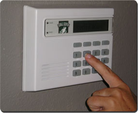
Hidden Panic Switch |
 |
Wily was
eating lunch when he got a call from an alarm company. They were installing more and
more home alarm systems. Business was good. But, a customer of theirs had an unusual
request. The homeowner wanted an invisible panic button. The alarm company
owner described the device as an electronic switch which would be positioned behind a wall
and activated when an adult human hand was pressed against the wall at that position.
Several such switches would be installed at key locations around the house. The
caller wanted to know if Wily could design something like that for them. Wily had
some ideas how he might do this so he agreed to take on the project.
 |
 |
|
Security System Control Panel |
Panic Button |
|
 |
 |
|
Burglar |
Hidden Switch Behind Wall |
|
|
The security company’s alarm system had multiple inputs, which could be
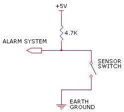
configured as panic switches. A typical switch interface circuit is shown below.
A 4.7K “pull-up” resistor is connected to the alarm’s +5v supply. The remote switches are
connected to the resistor and to circuit ground. When activated, the switch “sinks”
the +5v signal to ground. Based on the component values, the current through the
switch was about 1 milliamp and the threshold voltage for a valid switch closure was about
1.0v above ground. Wily was told that this two wire configuration was the standard
in the industry and was the alarm’s company’s preference. But, this configuration
made it a bit more difficult for any remotely activated panic button circuit to operate
without a secondary power source. A battery powered unit behind a wall would not be
practical. Also, some other power source, like an AC power adapter, would equally be
undesired. What Wily needed was a system which could detect a human hand pressed
against a wall and demanded so little power that it could draw power from the alarm’s
pull-up circuit. Wily figured that a device which required 100ua or less of current would
be best. |
 |
|
Alarm Sensor Interface Circuit |
|
|
Wily figured the best way to detect the human hand against a wall was with
a capacitance switch. The concept would be to mount the capacitance switch behind
the wall in key locations. An aluminum foil patch about 6 inches on a side would be glued
to the inside sheetrock wall, between the two by four studs. The patch would be
positioned about 6 feet off the floor, so small children or pets could not accidentally
trigger the alarm. Using earth ground as a reference, the capacitance between the
metal patch and ground would increase when the human hand was placed over the patch area.
Some quick calculations told Wily that the capacitance change would be about 10
picofarads. This was not much but with the right switch, it would be detectable. |
|
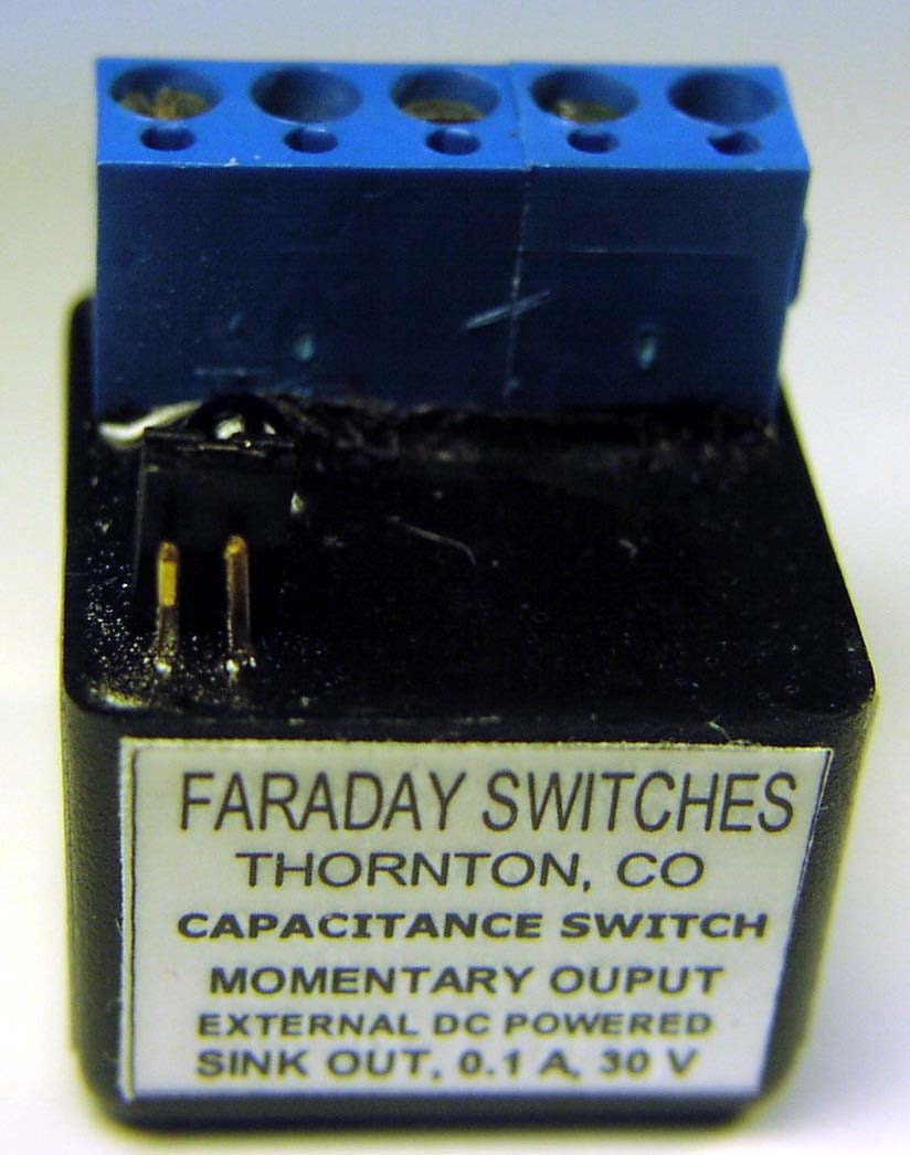
After doing some searches on the Internet. Wily found a very nice
capacitance switch to do the job. The QTFS3X from Faraday switches looked like a
perfect match for what Wily needed. The switch could be powered by a DC voltage down
to 3v. It required only 30ua of current. It was self calibrating so any changes in
the installation capacitance caused by humidity or temperature would be compensated for.
It could easily detect the 10pf of capacitance change. It was quite small and would easily
fit behind the wall. |
 |
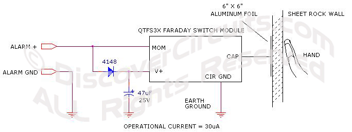
The circuit Wily used for this application is shown below. A
signal diode and capacitor routed power to the switches V+ terminal. The
momentary output terminal of the capacitance switch module was connected to the
alarm circuit’s sensor wire. The other wire from the alarm cable connected to
module’s circuit ground. When a hand was placed over the section of wall
containing the aluminum foil, the capacitance would increase. The switch module
would detect the sudden capacitance increase and would pull the sensor wire signal
to circuit ground. The energy stored in the capacitor would supply enough
power to the module for several seconds of operating, even as the input power was
shorted to ground. |
| |
|
|
|
|
A few weeks after Wily submitted his design to the alarm company, they
reported that the system worked perfectly. The alarm company indicated that they
would be offering this hidden switch as an option to future customers. |
|
|
|