|

|
|
|
|
|
|
|
|
Solar Powered Wireless Sensor |
 |
December 20, 2009 |
| Wily had just returned from his
morning walk when he got a call from a company in sunny Florida. The company was
desperate. They needed a DC power supply for a remote sensor they were developing
for one of their larger customers. The sensor was connected to a low power
microprocessor and a RF transmitter. When switched on, collected data was quickly
transmitted in a short burst. The transmitter drew a peak current of 1 Amp for about
0.01 seconds from a 3v supply. The transmitter was turned on only once every 10
seconds. |
|
|
This worked out to an average
current from the +3v supply of only 1ma. The sensor and processor added only another
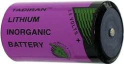
0.1ma of average current. OK, so far so good. The company first considered
using a single lithium ion battery, charged by a small solar panel but their customer
wanted a life of at least 10 years between battery replacements. Rechargeable
batteries didn’t last that long. They could get that kind of long-term performance from a
large disposable inorganic lithium battery bank but it would be enormous and expensive.
Could Wily come up with something better? |
| Wily asked the
caller a few more questions. He asked them if they considered a supercapacitor.
They said that they had but were not sure about how to properly use one. Wily told
the caller that a supercapacitor might do the job and might last longer than the 10 years
requested by the customer. The caller was pleased to hear that a solution was
possible. Wily and the caller talked some more. Wily collected some more
information and gave the caller a very rough idea of what it would cost to design and
build a working prototype of such a power supply. The caller agreed on the figure
and agreed to send Wily some money to start the project. |
| The first thing that
Wily had to do was to size the energy storage capacitor. Wily explored some capacitor
options. Many quality supercapacitors had a voltage rating of 2.7v. A bank of
four such caps would yield a 10.8v capacitor. Wily figured that if a good voltage
regulator were used, that the capacitor voltage could range from 10.8v to nearly 3v
without dropping out of regulation. So the total voltage range of the capacitor
would be from 10.8v to 3v for a delta of 7.8v. If the discharge current averaged
1.1ma over a period of about 24 hours, then capacitor would need to be sized at about 12
farads. If four capacitors were wired in series, then each device would need to be
about 50 farads. To insure a 10 year life, Wily thought that he should double that
figure to four 100 farad parts. With a capacitor voltage ranging from 10.8v to 3v,
better than 90% of the stored energy could be utilized before the capacitor voltage dipped
below 3v. |
| Wily looked around for some
supercapacitors. He had used some parts from Maxwell with success in the past.
Maxwell had a nice100 farad part that should do the trick. It was their model
BCAP0100. |
 |
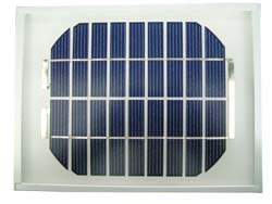
| The next thing on Wily's list was to
size the solar panel. The solar panel had to be large enough to continue to
supply all the power needed by the system during the day and charge the super
capacitor for night operation. Wily liked to use a 5% figure as the minimum
amount of power that a solar panel could deliver in overcast weather. |
| Wily used a 6 hour
figure for the time the typical solar panel would be exposed to sunlight each day.
The sensor, processor and RF transmitter required an average of 1.1ma for 24 hours
of each day. So, at a minimum, the solar panel needed to crank out 26.4
ma-hours of current. If the panel had only 6 hours to do that in, then it had
to put out 4.4ma at a minimum. If 4.4ma was the 5% level, then the full
sunlight current level would be about 88ma. |
|
| To charge the four
capacitors, Wily planned to use just the current from the solar panel. A single
schottky diode would isolate the panel from the 10.8v capacitor bank, so at night, current
would not flow from the capacitor back into the solar panel. Figuring a voltage drop
of about 0.5v, the panel needed a minimum voltage of about 12v. This would correspond to
about 24 cells. Many so-called “12v panels” in fact had 36 cells, in a 4 x 9
configuration and were designed to charge lead acid batteries, which needed over 14v.
Such a panel would most likely be rated at a voltage of about 17v. At full power the
panel would need to produce 88ma of charge current. So, this would mean the minimum
size panel would be about 1.5 watts. When looking around for solar panels, Wily
found many 12v panels rated for 2 to 3 watts. Wily suggested that his client use a
3 watt panel. This would give them some additional power margin. |
 |
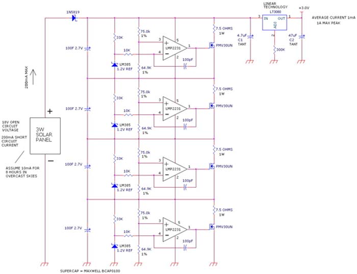
The third thing that Wily needed to
do was design a voltage limiting circuit for the four supercapacitors. Each
capacitor needed to be protected from being overcharged. Wily figured that a
shunt regulator set at 2.7v would do the job. This would insure that the four
capacitors would be fully balanced during charging process. Excess power from
the solar panel would be dissipated in the four regulators. At a combined
voltage of 10.8v and an expected current of about 200ma from the panel, each
regulator would have to dissipate about a half watt. If Wily sized the parts
for a 1W dissipation, he would have a good 50% margin. Wily's shunt regulator
circuit is shown below. |
|
| The fourth and final
item on Wily's list was to select the voltage regulator. A buck type switching
regulator would pull the power from the supercapacitor at a slower rate than a linear
regulator, when the RF transmitter was switched on, but a linear regulator would require
less standby current between transmitter activations. The duty cycle of the RF transmitter
was a low 0.1% so Wily was leaning toward a linear regulator. A linear regulator
would also produce less electrical noise and would be able to maintain regulation even
when the capacitor voltage approached 3v. Because the average power was fairly low,
Wily decided a linear regulator would work for this application. |
| Wily looked around
for a suitable voltage regulator. He wanted a device, which could supply the 1 Amp
of peak current and be able to maintain the 3v output with just 3.3v at the input.
Wily decided on the LT3080 from Linear Technology. |
|
|
|
|
|