|
Charge Pump Paradox |
 |
| Below is a pretty
simple circuit. At first blush it seems fairly logical. It was conceived
by a Discover Circuits visitor. He thought the circuit would allow the low
voltage from a single solar cell to charge a large super capacitor to a much higher
voltage using a charge pump method. But, would this circuit work? |
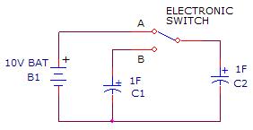
| In
his mind, the visitor imagined an electronic switch circuit which would toggle
between the two A and B states shown below. The capacitor C1 would be charged by the
solar cell until it reached about 0.5v, then it would be discharged into C3, using
C2 as a springboard to form a higher voltage. The switch would then change
states again and C3 would be switched back to C2, so the voltages matched. The idea
was to move the charge on the capacitor C1 to the cap C3, pumping up the voltage
across the capacitor C3. The cycle would repeat until C3 was charged up to any
desired voltage. For simplify, I show all three capacitors of the same size
but they could be any size. Again, this all sounds rational but after a few
minutes of staring at this circuit, I saw a problem. A big problem. The
circuit will not work and will in fact do nothing at all. Let’s see why. |
|
|
|
Charge pump circuits can be tricky. Things sometime just don’t work according
to plan. One of the things I leaned in college physics was that when dealing
with capacitor circuits, charge is conserved but energy is not. The charge Q
on a capacitor is simply CV, where Q is in coulombs, C is in farads and V is in
volts. So, a 1F capacitor charged up to 0.5v would have a charge of 0.5
coulombs. |
| The
energy E stored in a capacitor is 0.5CV^2. So, a 1uF capacitor charged up to 0.5v
would store 0.125 joules. |
| Now,
here is a real paradox in the world of capacitors. Let’s see what happens with the
circuit below. Two identical capacitors are connected to the circuit shown
below. Let’s start with the capacitor C1 fully discharged, meaning there is no
charge on it. Its voltage is zero. According to the equations above, the
charge on C2 is CV or 10 coulombs. The charge on C1 is zero. The energy stored
in C2 is 0.5CV^2 or 50 joules. Now, we throw the switch to position B. What
happens? In switch B position, the two capacitors are suddenly wired in parallel.
If the energy were conserved, since the total capacitance is now 2F, the voltage
should be 7.07 volts. But, as I said, charge is conserved, so when the
capacitance suddenly jumps from 1F to 2F, the charge is shared between the two caps
and the end voltage is really 5 volts, with a final energy state of only 25 joules.
Holy cats! What happened to the other 25 joules? Gone! The physics
says that when two capacitors are brought together like this, much of the stored
energy is lost. |
|
|
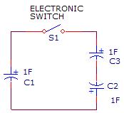
| Now,
let’s get back to the original circuit. When the switch is moved from position
B to A, the circuit looks like the one on the left below. The two capacitors
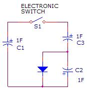
C3 and C2 are wired in series but C2 has a reversed polarity. Even it you
added a diode in parallel with C2 as shown in the figure on the right, the result is
pretty much the same. For this discussion, we will leave the diode out and just say
that the polarity of the capacitor C2 is opposite to C3. Based on the
discussion above, charge is conserved, so the charge on C1 is shared between the
three capacitors, with C2 and C3 wired in series. This series-parallel circuit
puts the total capacitance at 1.5F. So, if C1 were to be charged up to 0.5v with a
charge of 0.5 coulombs the voltage would suddenly drop to 0.33 volts. C2 and C3
would split the voltage so C3 would be charged to 0.167v positive and C2 would be
charged to 0.167v negative. |
|
|
| OK,
now in our original circuit, in switch position B the capacitors C2 and C3 are
switched in parallel again. But, wait. If C3 and C2 are identical and have the same
charge but opposite polarity, what happens when they are connected together?
Yes! The charge stored in one is canceled by the opposite charge in the second.
Bang! All the energy stored is lost to the ether. |
| So,
this simple circuit seems like it should work but instead it simply swallows up all
the energy from the solar cell and gives nothing in return. It would do the
same with both smaller and large capacitors. |
| In
conclusion, I have yet to see a charge pump circuit which can move charge from one
capacitor to other capacitors without going through a doubler or tripler
configuration. Most commercial charge pump converters use variations of
voltage doublers to produce a higher output voltage. With a careful design,
the circuits can be fairly efficient but often they are only about 50% efficient.
Inductors and transformers work much better when trying to increase one low voltage
to a higher voltage. |
|
|
|